

Vertex USB GUI for Windows PC
The Vertex USB GUI for Windows PC: every tab and option explained, from EDID MANAGER and SCALER to HDR, AVI/VSI and Dolby Vision InfoFrames.
ALL CHAPTERS
The USB GUI is compatible with all Microsoft Windows version from Win XP to Win 10.
Make sure you have installed the right Silabs driver based on your Windows version and USB port as described in p.19
→ See: USB driver (Windows)You can download the latest GUI version for your Vertex device from the Download Tab on the Vertex Product page: here. Always run latest FW when running latest GUI to benefit from all new features.
The USB GUI for Windows PC allows the following control:
- Display Information on Source device when available.
- Display Input signal resolution, refresh rate and bandwidth.
- Display Input signal Color Space and Deep Color.
- Display Input signal encryption.
- Display Input signal detected Audio type.
- Display Information on Sink device when available.
- Display Output signal resolution, refresh rate and bandwidth.
- Display Output signal Color Space and Deep Color.
- Display Output signal encryption.
- Display the Firmware version and Windows GUI revision.
- Display Active input information.
- Switch Active Input or enter/exit Matrix modes.
- Select EDID Mode (Sink, Custom, Fixed)
- Select the default EDID table from a selection of 100 preloaded EDID banks.
- Use similar or different EDID for each input.
- Select forced flags for Automix mode. (2.0, 5.1, 7.1 Full, Native, Top Max, BT.2020/xvYcc, HDR10+, HLG, DV Force, DV Remove, DV Limit, no 3D, no YCbCr)
- Select Automix Algo
- Sniff EDID from connected sink devices. (Read EDID from TOP and BOT output)
- Read, Write, Load, and Save and Upload any custom EDID bank.
- Define Scaling rules (No Scaling, Custom Scaling, Auto Scaling)
- Select preferred Custom Scaling Modes
- Select Scaling rules from available 4K30 presets
- Select Scaling rules from available 4K60 and 4K60 4:2:2 presets
- Set preferred Scaling options (Downscale, Thru and Up)
- Defines Color Space and Deep Color for Downscale, Thru and Up.
- Display Captured HDR Metadata.
- Send Live HDR Metadata created with Custom HDR metadata generator.
- Autofill CRC for HDR infoframe.
- Disable HDR by cancelling all incoming HDR metadata (JVC PJ mode)
- Display Captured AVI and Vendor Specific InfoFrame.
- Send Custom AVI and Vendor Specific Infoframe.
- Disable AVI and VSI.
- Save Dolby Vision mandatory string from connected sink.
- Display captured SPD, Audio, HDMI Vendor Specific and HDMI Forum VSIF Infoframe.
- Enable/Disable OSD notification.
- Set OSD location, color, transparency, background.
- Select OSD info to be displayed (Source, Video Field, Video IF, HDR RX/TX, HDR IF, Audio, RX HDR).
- Select OSD timer for OSD fade out.
- Enable or Disable OSD Mask.
- Set location and OSD mask transparency.
- Enable or Disable OSD custom text.
- Set location for OSD custom text.
- Edit OSD custom text.
- Send Live HDMI CEC command.
- Turn ON/OFF CEC processing.
- Define CEC ID# (Either AVR ID#5 for ARC feature or processor ID#14)
- Turn ON or OFF the Autoswitch feature.
- Set Input Priority for Autoswitch mode (Normal/Forced)
- Select HDCP output revision.
- Enable or disable the Side Logos.
- Enable or disable the OLED
- Rotate OLED by 180 degrees
- Reverse OLED colors
- Set OLED fade out timer
- Issue Hotplug (Soft Reset)
- Set OLED Startup page
- Reset the unit to Factory Default.
- Reset EDID to Factory Default.
- Import or Export Config file.
TOP SECTION
The TOP SECTION of the USB GUI for Windows PC:

The right boxed area will provide you with the following information:
- FW: 1.14.1.20
- on the top right corner indicates the current FW version of your Vertex unit.
- GUI: 1.14
- on the top right corner indicates the current Windows GUI version in use.
- Source Info
- When available it will display information about the source device in use.
- RX0
- Display Input signal resolution at RX0 input; refresh rate, color, bandwidth and HDCP information.
- AUD0
- Display sound information for the RX0 input.
- RX1
- Display Input signal resolution at RX1 input; refresh rate, color, bandwidth and HDCP information.
- AUD1
- Display sound information for the RX1 input.
- TX1
- Display Status or Output signal resolution at TX1; refresh rate, color, bandwidth, HDCP and EDID
- TX0
- Display Status or Output signal resolution at TX0; refresh rate, color, bandwidth, HDCP and EDID
On the left, below the Vertex logo:
- Active Input
- Allow you to select the current active input port or enter both Matrix modes available. Similarly to what you can do from the push button on the unit (see page 9)
EDID MANAGER
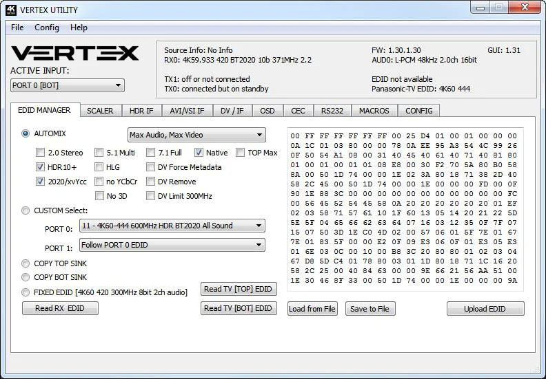
The EDID MANAGER section of the USB GUI for Windows PC:

- Automix Mode
- Create EDID based on mutual capabilities so both sinks will always show a picture and audio. Some Flags can be checked or unchecked so you can force and override some parameters to match your needs. Ex: If your TV is stereo and your AVR full sound and both are connected to each Vertex outputs port, then by default, Automix will report Stereo as sound capabilities, by checking Full Audio flag you will force Automix to always report Full Audio no matter the real sound capabilities of the connected sink devices.
- Automix Algo
- Select the mixing algo of your choice, available algo are: Min Mixed Capabilities, Max Audio/Min Video, Top Output Priority, Bot Output Priority, Max Audio/Max Video (default)
- 2.0 Stereo
- Force the created automix EDID to present stereo sound capabilities.
- 5.1 Multi
- Force the created automix EDID to present 5.1 multi-channel sound capabilities.
- 7.1 Full
- Force the created automix EDID to present Full 7.1 sound capabilities.
- Native
- Force the created automix EDID to present the setup native sound capabilities.
- TOP MAX
- Force the automix EDID to present the max audio capabilities from sink at top output.
- HDR 10+
- Force the automix EDID to present HDR10+ support.
- HLG
- Force the automix EDID to present the HLG support.
- 2020/xvYCC
- Force the automix EDID to present BT2020 and xvYCC support.
- no YCbCr
- Force the automix EDID to present no support for YCbCr (useful to force RGB).
- no 3D
- Force the automix EDID to present no support for 3D.
- DV Force Metadata
- Force the automix EDID to present Dolby Vision support.
- DV Remove
- Force the automix EDID to present no support for Dolby Vision.
- DV Limit 300MHz
- Force the automix EDID to only present support for Dolby Vision at 300MHz.
- Custom Use / BT
- Pick and use EDID from a selection of preloaded EDID tables or load any EDID bank of your choice. By default the selected EDID table is a 4K60 4:4:4 600MHz with Full Audio capabilities. Leave the slide in this position to allow remote control via USB/IR or Android/iOS APP and/or to pick and use any from up to 100 different EDID tables available (4K60 4:4:4 HDR, 4K60 4:2:0 10bit, see p.13 for the full list). When you select an EDID bank from the dropdown list of preloaded EDID banks, there is nothing else to do, once you click one, the EDID of your choice will be loaded and HPD events will reset the signal to present your selected EDID automatically. Each input can have an individual EDID assigned.
- Copy TOP Sink
- Use EDID from TOP Sink
- Copy BOT Sink
- Use EDID from BOT Sink
- Fixed EDID with L/R Audio
- This mode is a 4K60 4:2:0 8b 300MHz stereo EDID table. It can be used as a security EDID to ensure a picture in every setup/situation. (Except for FHD and 4K30 Max display)
- Read RX EDID
- This option could be useful if for example you want to double check the build capabilities of an Automix EDID in your setup using external software such as AWEE (AW EDID Editor from Analog Way). In such case, you would simply use the Read Vertex EDID button and then the Save to File button in order to be able to open the EDID file with an external EDID editor software.
- Read TV [TOP] EDID
- Allow you to sniff the EDID from the sink device connected to the TOP output port of your Vertex unit. You could then use it as the Custom EDID by using the Upload EDID to Vertex button or export it as a file using the Save to File button in order to be able to open the EDID file with an external EDID editor software.
- Read TV [BOT] EDID
- Allow you to sniff the EDID from the sink device connected to the BOTTOM output port of your Vertex unit. You could then use it as the Custom EDID by using the Upload EDID to Vertex button or export it as a file using the Save to File button in order to be able to open the EDID file with an external EDID editor software.
- Load from File
- Allow you to open and load any EDID file of your choice. You could then use it as the Custom EDID by using the Write EDID to Vertex button.
- Save to File
- Allow you to save the current EDID into a file for backup or for editing using external software such as AWEE (AW EDID Editor from Analog Way).
- Upload EDID
- This button will write the current manually uploaded EDID file into Vertex custom bank.
SCALER
The SCALER section of the USB GUI for Windows PC:

- No Scaling
- Set your unit to No Scaling for the signal to pass-through untouched
- Custom Scaling
- Set your Vertex unit to Custom Scaling to manually define the scaling parameters. You can select between various type of resolutions, color space and deep color settings for both the upscale and downscale output ports.
- Available Color Space options
- Follow Input (default), RGB FULL, RGB BT2020, 4:4:4 BT.709, 4:4:4 BT2020, 4:2:2 BT.709, 4:2:2 BT2020, 4:2:0 BT.709, 4:2:0 BT2020.
- Available Deep Color options
- Follow Input (default), 8-bit/24-bit, 10-bit/30-bit, 12-bit/36-bit, 16-bit/48-bit
- Auto Scaling
- Set your unit to Auto Scaling to use automatic pre-sets for TX1 [TOP output port]. By default unit will use auto-sense.
- 4K60 PRESET
- This forces any 4k60 input to come out as 4k60 420 8bit 300MHz or 1080p60 444 8/10/12-bit. A neat profile for people who only have a 300MHz display with 4K60 420 8-bit support. If EDID allows the player to send HDMI 2.0 formats, such as all HDR modes, they will be accepted by the display due to Vertex scaling/chroma changes.
- 4K60 422 HDR PRESET
- This forces 4K60 420 HDR input to come out as 4K60 420 10-bit, 4k60 420 8-bit 300MHz or 1080p60 444 8/10/12-bit. A neat profile for people who only have a 300MHz display with 4K60 420 8-bit support. If EDID allows the player to send HDMI 2.0 formats, such as all HDR modes, they will be accepted by the display due to Vertex scaling/chroma changes.
- 4K30 PRESET
- This forces any 4k24/25/30 to come out as 4k24/25/30 444 8-bit 300MHz, 1080p30 444 8/10/12-bit or 4k24/25/30 422 12-bit 300MHz. A neat profile if you have a 300MHz display. If EDID allows the player to send HDMI 2.0 formats, such as all HDR modes, they will be accepted by the display due to Vertex scaling/chroma changes.
- NO UPSCALING
- By default when using Auto Scaling, Vertex will upscale TX0 [BOT output port] when possible, to disable this behavior or to let the sink/display performs the upscaling, you can check this option.
HDR INFOFRAME
The HDR INFOFRAME section of the USB GUI for Windows PC:
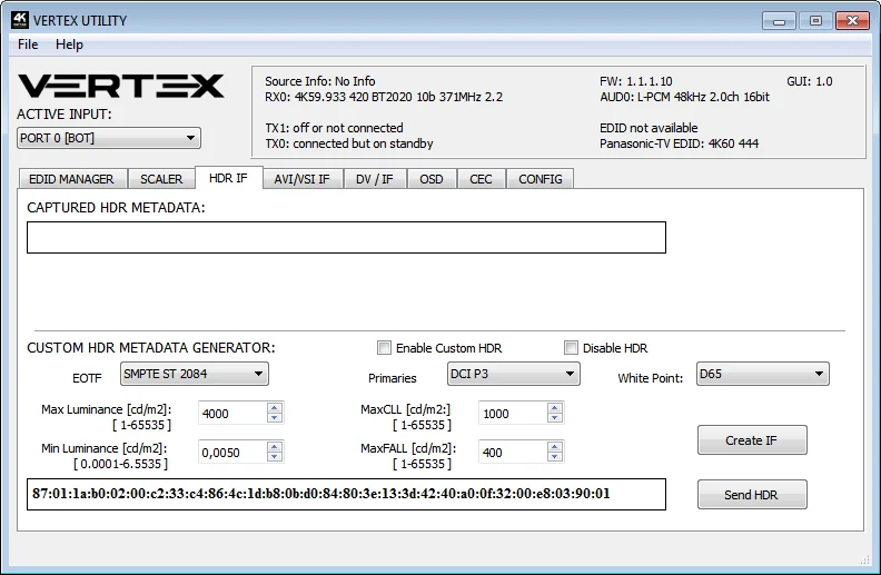
- CAPTURED HDR METADATA
- If the source at input is sending HDR InfoFrame metadata then the information is captured, extracted and displayed in this text box on GUI. HDR metadata is also deciphered and displayed in human readable format on both the Windows GUI and OSD.
- CUSTOM HDR METADATA GENERATOR
- This GUI section will allow you to create your own custom HDR metadata and inject it on the current signal by adding it or replacing the existing HDR metadata.
- ENABLE CUSTOM HDR
- Unchecked by default, once activated it will turn ON the HDR mode of any HDR display. Upon clicking ENABLE CUSTOM HDR the CUSTOM HDR IF that is defined by dropdown and input field and then created and displayed in the text box gets sent. This way you can define what the InfoFrame actually is. This is stored also in Vertex and is persistent over hotplugs and power cycles.
- Disable HDR
- Once activated this option will allow Linker to intercept and cancel all incoming HDR metadata. This mode was introduced to allow JVC PJ owners to apply their own Gamma curves for HDR content and allow their PJ DI to work when content is HDR.
- EOTF
- Select between SDR Luminance Range, HDR Luminance Range, HLG ITU-R BT.2100-0 or SMPTE ST 2084 values to be used in the custom HDR metadata creation.
- Primaries
- Select between DCI P3, ITU-R BT 709-5 or ITU-R BT2020-2 values to be used in the custom HDR metadata creation.
- White Point
- Select the white point value to be used in the custom HDR metadata creation.
- Max Luminance
- Select the Max Luminance value to be used in the custom HDR metadata creation (valid from 1 to 65535)
- MaxCLL
- Select the MaxCLL value to be used in the custom HDR metadata creation (valid from 1 to 65535)
- Min Luminance
- Select the Min Luminance value to be used in the custom HDR metadata creation (valid from 1 to 65535)
- MaxFALL
- Select the MaxFALL value to be used in the custom HDR metadata creation (valid from 1 to 65535)
- Create IF
- Use the previous defined values to create the Custom HDR metadata.
- Send HDR
- Send the custom created HDR metadata. Please note that upon clicking, Enable Custom HDR will get activated automatically, to stop the sending of the custom HDR metadata, uncheck Enable Custom HDR. If Enable Custom HDR is activated then by pressing the Send HDR button, the metadata injection does not stop, it just changes values, useful to avoid TV resync.
- Public API/DLL
- We have created a set of DLL/API package for Vertex so anyone can interface their Windows software with Vertex capabilities and build evaluation, testing, measurement, calibration and content creation workflows system.
- IR/RS232
- Vertex can be fully controlled via IR or from any serial based computer such as Win, Mac or Linux using RS232 interface. Complete list of IR and RS232 commands are included as a text file for convenience on all Firmware updater and GUI utility package.
AVI/VSI IF
The AVI/VSI IF section of the USB GUI for Windows PC:
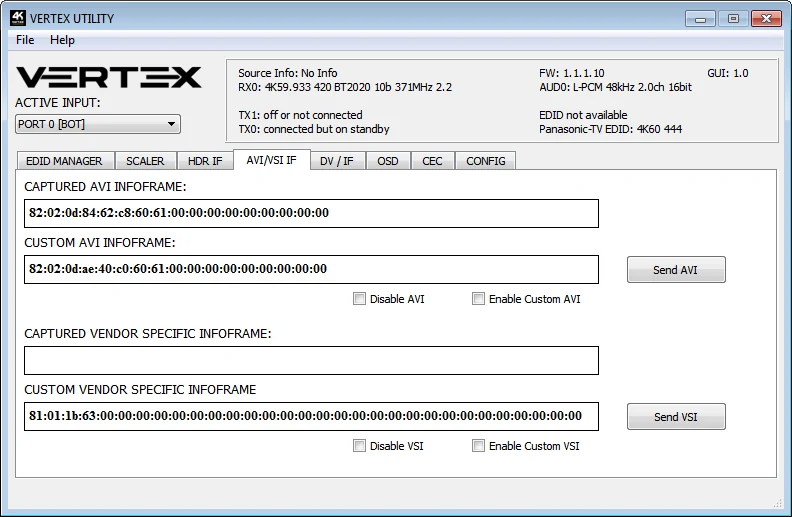
- CAPTURED AVI INFOFRAME
- If the source is sending AVI infoFrame then the information is captured, extracted and displayed in this text box on GUI.
- CUSTOM AVI INFOFRAME
- Enter the AVI Infoframe of your choice in this text field in HEX format. If you are not sure about how to format your AVI Infoframe, we recommend you to visit our Infoframe Injection thread in our support forum. (Advanced Users only)
- Send AVI
- Replaces the current incoming AVI with the custom defined one in the text box. This way customer can for example activate BT2020 mode in the TV even though content doesn't sent the correct InfoFrame. This string is also saved in Vertex and is persistent over hotplugs and power cycles. The AVI mod is really meant for advanced users only because incorrect values can blank the screen and since the settings are saved even power up won't help until reset. Please note that upon clicking, Enable Custom AVI will get activated automatically, to stop the sending of the custom AVI infoframe, uncheck Enable Custom AVI. If Enable Custom AVI is activated then by pressing the Send AVI button, the infoframe injection does not stop, it just changes values, useful to avoid TV resync.
- Disable AVI
- When checked, Disable AVI will prevent AVI InfoFrame from source to reach the connected sink at Vertex output and also stop sending Custom AVI if set previously. This feature can be useful for some DVI display or some monitor that do not work well when receiving an AVI InfoFrame.
- Enable Custom AVI
- Upon clicking Enable Custom AVI, the IF that is defined in the Custom AVI text box gets used. This way you can define what the InfoFrame actually is. This is stored also in Vertex and is persistent over hotplugs and power cycles. This way customer can for example activate BT2020 mode in the TV even though content doesn't sent the correct InfoFrame. The AVI mod is really meant for advanced users only because incorrect values can blank the screen and since the settings are saved even power up won't help until reset.
- CAPTURED VENDOR SPECIFIC INFOFRAME
- If the source is sending Vendor Specific Infoframe then the information is captured, extracted and displayed in this text box on GUI.
- CUSTOM VENDOR SPECIFIC INFOFRAME
- Enter the Vendor Specific Infoframe of your choice in this text field in HEX format. If you are not sure about how to format your AVI Infoframe, we recommend you to visit our Infoframe Injection thread in our support forum. (Advanced Users only)
- Send VSI
- Replaces the current incoming VSI with the custom defined one in the text box. This string is also saved in Vertex and is persistent over hotplugs and power cycles. Please note that upon clicking, Enable Custom VSI will get activated automatically, to stop the sending of the custom VSI infoframe, uncheck Enable Custom VSI. If Enable Custom VSI is activated then by pressing the Send VSI button, the infoframe injection does not stop, it just changes values.
- Disable VSI
- When checked, Disable VSI will prevent VSI InfoFrame from source to reach the connected sink at Vertex output and also stop sending Custom VSI if set previously.
- Enable Custom VSI
- Upon clicking Enable Custom VSI, the IF that is defined in the Custom VSI text box gets used. This way you can define what the InfoFrame actually is. This is stored also in Vertex and is persistent over hotplugs and power cycles.
- Public API/DLL
- We have created a set of DLL/API package for Vertex so anyone can interface their Windows software with Vertex capabilities and build evaluation, testing, measurement, calibration and content creation workflows system.
- IR/RS232
- Vertex can be fully controlled via IR or from any serial based computer such as Win, Mac or Linux using RS232 interface. Complete list of IR and RS232 commands are included as a text file for convenience on all Firmware updater and GUI utility package.
DV/IF
The DV/IF section of the USB GUI for Windows PC:
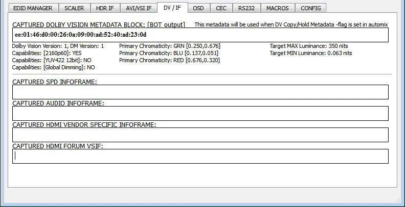
- CAPTURED DOLBY VISION METADATA BLOCK
- Vertex will automatically sniff, display and save any Dolby Vision mandatory string from a connected sink at BOT output. Once stored, this mandatory string can be used in Automix to ensure that the DV stream from the source is compatible with the sink. Once the DV string of a display is saved, you can insert other equipment like an AVR in between in the chain and still have the right DV signal passthru to the sink. Additionally, the stream is fully deciphered in human readable format.
- CAPTURED SPD INFOFRAME
- Display Source Product InfoFrame.
- CAPTURED AUDIO INFOFRAME
- Current Audio Format information, if PCM this usually gives the sample rate and number of speakers, if bitstream then usually this infoframe just inform the default which is “refer stream header”
- CAPTURED HDMI VENDOR SPECIFIC INFOFRAME
- Display HDMI Vendor Specific InfoFrame.
- CAPTURED HDMI FORUM VSIF
- Display HDMI2.0 version of HDMI VSIF
OSD
The OSD section of the USB GUI for Windows PC:
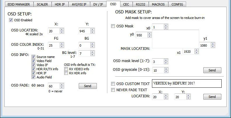
- OSD Enabled
- Enable or Disable the OSD feature of Vertex.
- OSD LOCATION X, Y
- Set the X and Y value of the OSD location at 1080p, values are multiplied by 2 when the stream is 4K
- OSD COLOR INDEX FG, BG, BG level
- Set the Text Color, Background Color and Background transparency for the OSD.
- OSD INFO
- Select or unselect the information that must be displayed on your Vertex OSD. Available options are: Source name, Video Field, Video IF, HDR TX/TX info, HDR IF, Audio field, RX Video info, RX HDR info.
- OSD FADE
- Set the timer before OSD fade out, 0 = never.
- SEND
- For any changes in the above parameters, click SEND to upload them to your Vertex unit.
- OSD Mask
- Enable or Disable the use of OSD Mask.
- MASK LOCATION x0,y0,x1,y1
- Defines the coordinates of the top left and bottom right corner of your OSD Mask at 1080p. Values are multiplied by 2 when the stream is 4K
- OSD Mask level
- Select the level of transparency for your OSD Mask. Value range is from 1 to 7.
- OSD grayscale
- Select the level of grayscale for your OSD Mask. Value range is from 0 to 15.
- SEND
- For any changes in the above parameters, click SEND to upload them to your Vertex unit.
- OSD CUSTOM TEXT
- Enable or disable the OSD Custom Text, once activated, the custom text defined in the text field will be displayed on screen.
- NEVER FADE TEXT
- If you want to keep the OSD Custom text even after OSD info faded away, make sure this option is enabled.
- LOCATION X,Y
- Set the X and Y value of the OSD Custom Text at 1080p, values are multiplied by 2 when the stream is 4K
- SEND
- For any changes in the above parameters, click SEND to upload them to your Vertex unit.
CEC Commander
The CEC COMMANDER section of the USB GUI for Windows PC:

- CEC COMMAND
- Enter the CEC command of your choice in this text field in HEX format.
If you are not sure about how to format your command, we recommend you to visit the very well done cec-o-matic website made by Kwikwai.
- SEND CEC
- By clicking this option, the CEC command you entered in the CEC COMMAND text field will be sent out by the Vertex unit.
- VERTEX CEC DEVICE TYPE
- Video Processor by default (ID#5)
CEC ENABLED must be ON in order to apply the selected dropdown options to the Vertex unit.
Video Processor (Default) is the device type to choose if you have an AVR in your setup and if you want to use that AVR for ARC or CEC.
Audio System w/ARC is the device type to choose if you want Vertex ARC feature to be ON (Sound from TV ARC to Vertex 5.1 Optical Out or Jack Analog Stereo output. You can also use this method if you want Vertex to replace your AVR as CEC Commander.
- CEC ENABLED
- Unchecked by default, once activated it allows Vertex to answer and process CEC requests and commands and appear on the CEC network map. Uncheck it if you do not want Vertex to answer external CEC requests or process Internal CEC commands. Unchecking will remove Vertex from the Root network map but CEC commands for connected sinks or sources will still pass-thru.
- ARC ALLOW DD+/ATMOS
- If your AVR is capable of accepting 192khz Audio via its optical input, you can use Vertex to extract DD+ and Atmos for TV embedded streaming APPS and forward it to your AVR via the Vertex optical output. Only a very few AVR on the market can support 192khz via optical.
A few examples for testing CEC commands are provided on the GUI.
Using the Android or iOS APP, it is possible to create custom menu for CEC commands.
Feel free to join our support server of the forums in order to know more about it.
RS232
The RS232 section of the USB GUI for Windows PC:
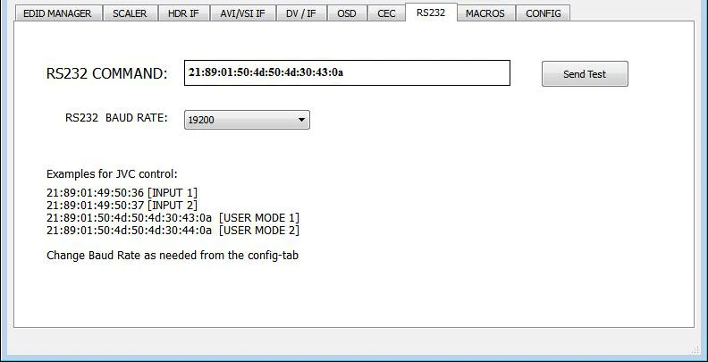
- RS232 COMMAND
- Allow you to test RS232 command to make sure your unit is properly configured and ready to communicate via RS232.
- Send Test
- Once RS232 command have been entered, use this button to send it out.
- RS232 BAUD RATE
- Set the RS232 link speed (default 19200)
Macros
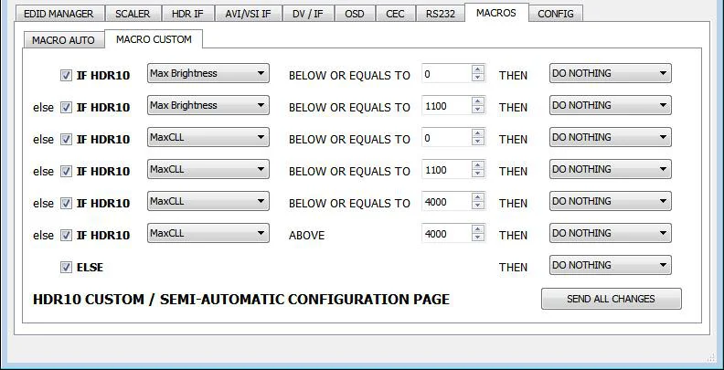
The MACROS section of the USB GUI for Windows PC:
With the help of power users from the community, special automatic and custom macro has been developed for JVC Projectors. Kindly please refer to instructions posted here.

Config
The CONFIG section of the USB GUI for Windows PC:

- AUTO SWITCH
- When activated, the Auto Switch feature will force the Vertex unit to automatically switch to the active signal if the selected signal is lost.
- PRIORITY
- When in FORCED input priority mode, as soon as a new active input is detected, Vertex will switch to it.
- HDCP VERSION
- Allow you to select/force the HDCP revision of the Output Ports. Similarly to what you can do from the push button on the unit (see page 10)
- LOGO LED
- Enable by default, GREEN Vertex side logo can be turned ON/OFF at will. Some users might found Vertex side logo visually disturbing in their HT setup. You have the possibility to turn them off.
- OLED DISPLAY
- Enable by default, Vertex OLED display can be turned ON/OFF at will. Some users might found the Vertex OLED display visually disturbing in their HT setup. You have the possibility to turn it off.
- ROTATE 180 DEG
- OFF by default, based on your setup, you might prefer to flip the OLED display, once activated, this option will flip the Vertex OLED.
- REVERSE COLORS
- OFF by default, once activated this option will reverse the Vertex colors.
- OLED FADE
- Allow you to define a custom timing in seconds before OLED FADE, set it to 0 for OLED to always stay active.
- ISSUE HOTPLUG
- Click Send button to perform a soft-reset in your setup.
- HTPC MODE
- Useful if you have trouble with windows display and icons when resuming from stand-by mode.
- START UP MENU PAGE
- You can select which one of the 5 info pages available will be displayed first as default.
- Page 1: Info [Default]
- Page 2: RX Info
- Page 3: HDR 1
- Page 4: HDR 2
- Page 5: IF info
- L/R AUDIO CONTROL
- This option will only be available on upcoming Vertex unit running FW1.30.1.30 as mandatory step. L/R Audio control options will be grayed out on current and first generation. If your unit is compatible, you will be able to adjust the Analog Stereo output from this section. Volume, Bass and Treble control are available.
- MUTE BOT TX AUDIO
- If you use an AVR at TOP output, you might want to disable sound going to equipment connected at BOT output. Here you can mute the BOT output sound.
- CLEAR ALL SETTINGS TO FACTORY DEFAULTS
- Similar as [LP] Long Press on the RESET button (see page 7). Click the available check box to clear all settings to factory defaults and type RESET in the test field. Finally click the OK button and unit will be reset to factory defaults. Vertex power cycle needed.
- EDID FACTORY RESET
- Click the available check box to clear all EDID settings to factory defaults and type RESET in the test field. Finally click the OK button and unit EDID will be reset to factory defaults.
Config Import/Export
CONFIG Import/Export section of the USB GUI for Windows PC:
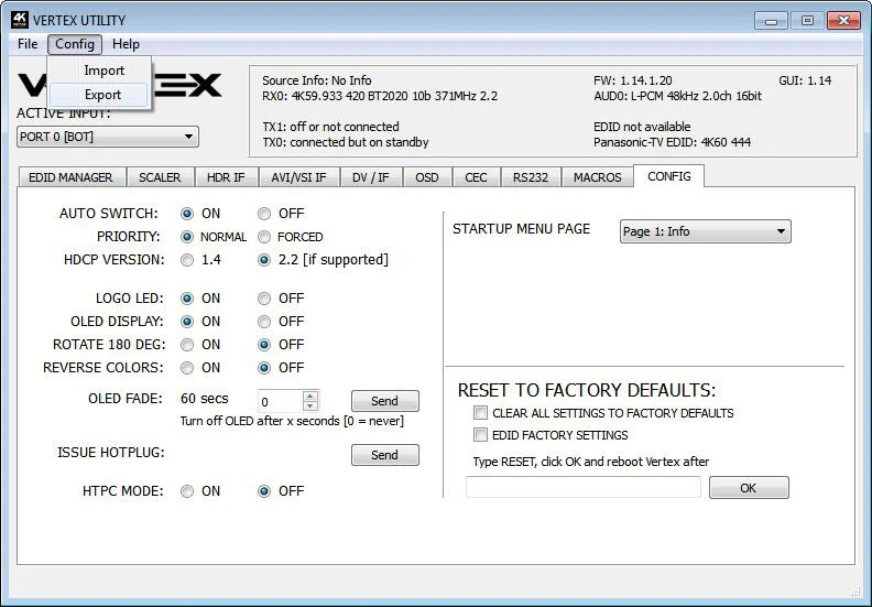
By using the [CONFIG] > [EXPORT] option, you will be able to save the current Vertex configuration and settings in a text file.
The file can then be shared with others, for support reason or simply to be loaded back after a newer firmware update by using [CONFIG] > [IMPORT] option.
Exported config file will present the active signal information, the EDID set for each RX and TX as well as the list of parameters that can be edited in the text file directly before importing the file back.
################################################################
# HDFURY VERTEX CONFIGURATION FILE
# [23.2.2018 16:19:25]
################################################################
# STATUS INFO START - DO NOT MODIFY VALUES
################################################################
FW: 1.30.1.30, GUI: 1.31, PCB 1
RX0: 4K59.933 422 BT2020 12b 593MHz 2.2
AUD0: L-PCM 48kHz 2.0ch 24bit
TX0: 4K59.933 422 BT2020 12b 593MHz 2.2
TX1: 1080P59.933 444 BT709 8b 148MHz 1.4
SONY TV  *00 EDID: 4K60 444 HDR BT2020
DENON-AVRHD EDID: 4K24 444
Source Info: No Info
AVI: 82:02:0d:94:32:e8:60:61:00:00:00:00:00:00:00:00:00
AUDIO: 84:01:0a:70:01:00:00:00:00:00:00:00:00:00

#RX0 EDID
00 FF FF FF FF FF FF 00 4D D9 04 7A 01 01 01 01
01 1C 01 03 80 90 51 78 0A 0D C9 A0 57 47 98 27
12 48 4C 21 08 00 81 80 A9 C0 71 4F B3 00 01 01
01 01 01 01 01 01 08 E8 00 30 F2 70 5A 80 B0 58
8A 00 9F 29 53 00 00 1E 02 3A 80 18 71 38 2D 40
58 2C 45 00 9F 29 53 00 00 1E 00 00 00 FC 00 53
4F 4E 59 20 54 56 20 20 2A 30 30 0A 00 00 00 FD
00 17 3E 0E 88 3C 00 0A 20 20 20 20 20 20 01 EE
02 03 74 F0 5E 61 60 5D 5E 5F 62 1F 10 14 05 13
04 20 22 3C 3E 12 16 03 07 11 15 02 06 01 65 66
23 1D 26 38 0D 7F 07 15 07 50 3D 1F C0 57 06 00
0F 7F 07 5F 7E 01 67 7E 00 4D 02 00 83 5F 00 00
6E 03 0C 00 31 00 B8 3C 2F 00 80 01 02 03 04 67
D8 5D C4 01 78 80 01 E3 05 C3 01 E2 00 CB E5 0F
03 00 00 06 E3 06 07 01 EB 01 46 D0 00 45 03 80
86 60 76 8F 00 00 00 00 00 00 00 00 00 00 00 65

#RX1 EDID
00 FF FF FF FF FF FF 00 4D D9 04 7A 01 01 01 01
01 1C 01 03 80 90 51 78 0A 0D C9 A0 57 47 98 27
12 48 4C 21 08 00 81 80 A9 C0 71 4F B3 00 01 01
01 01 01 01 01 01 08 E8 00 30 F2 70 5A 80 B0 58
8A 00 9F 29 53 00 00 1E 02 3A 80 18 71 38 2D 40
58 2C 45 00 9F 29 53 00 00 1E 00 00 00 FC 00 53
4F 4E 59 20 54 56 20 20 2A 30 30 0A 00 00 00 FD
00 17 3E 0E 88 3C 00 0A 20 20 20 20 20 20 01 EE
02 03 74 F0 5E 61 60 5D 5E 5F 62 1F 10 14 05 13
04 20 22 3C 3E 12 16 03 07 11 15 02 06 01 65 66
23 1D 26 38 0D 7F 07 15 07 50 3D 1F C0 57 06 00
0F 7F 07 5F 7E 01 67 7E 00 4D 02 00 83 5F 00 00
6E 03 0C 00 32 00 B8 3C 2F 00 80 01 02 03 04 67
D8 5D C4 01 78 80 01 E3 05 C3 01 E2 00 CB E5 0F
03 00 00 06 E3 06 07 01 EB 01 46 D0 00 45 03 80
86 60 76 8F 00 00 00 00 00 00 00 00 00 00 00 64

#TX0 EDID
00 FF FF FF FF FF FF 00 4D D9 04 7A 01 01 01 01
01 1C 01 03 80 90 51 78 0A 0D C9 A0 57 47 98 27
12 48 4C 21 08 00 81 80 A9 C0 71 4F B3 00 01 01
01 01 01 01 01 01 08 E8 00 30 F2 70 5A 80 B0 58
8A 00 9F 29 53 00 00 1E 02 3A 80 18 71 38 2D 40
58 2C 45 00 9F 29 53 00 00 1E 00 00 00 FC 00 53
4F 4E 59 20 54 56 20 20 2A 30 30 0A 00 00 00 FD
00 17 3E 0E 88 3C 00 0A 20 20 20 20 20 20 01 EE
02 03 65 F0 5B 61 60 5D 5E 5F 62 1F 10 14 05 13
04 20 22 3C 3E 12 16 03 07 11 15 02 06 01 65 66
2C 0D 7F 07 15 07 50 3D 07 BC 57 06 00 83 0F 00
00 6E 03 0C 00 30 00 B8 3C 2F 00 80 01 02 03 04
67 D8 5D C4 01 78 80 01 EB 01 46 D0 00 45 03 80
86 60 76 8F E2 00 CB E3 05 FF 01 E5 0F 03 00 00
06 E3 06 0D 01 01 1D 00 72 51 D0 1E 20 6E 28 55
00 9F 29 53 00 00 1E 00 00 00 00 00 00 00 00 A8

#TX1 EDID
00 FF FF FF FF FF FF 00 11 EE 2A 00 01 01 01 01
00 16 01 03 80 90 51 78 0A 0D C9 A0 57 47 98 27
12 48 4C 21 08 00 81 80 A9 C0 71 4F B3 00 01 01
01 01 01 01 01 01 02 3A 80 18 71 38 2D 40 58 2C
45 00 9F 29 53 00 00 1E 01 1D 00 72 51 D0 1E 20
6E 28 55 00 9F 29 53 00 00 1E 00 00 00 FC 00 44
45 4E 4F 4E 2D 41 56 52 48 44 0A 20 00 00 00 FD
00 30 3E 0E 46 0F 00 0A 20 20 20 20 20 20 01 81
02 03 54 F0 5F 5D 5E 5F 62 1F 10 14 05 13 04 20
22 3C 3E 12 16 03 07 11 15 02 06 01 0E 23 0F 24
1D 25 1E 26 35 0F 7F 07 3D 1E C0 15 07 50 5F 7E
01 57 06 00 67 7E 00 4D 02 00 83 5F 00 00 6E 03
0C 00 41 00 B8 3C 2F 00 80 01 02 03 04 E3 05 1F
01 E2 00 F9 01 1D 80 18 71 1C 16 20 58 2C 25 00
9F 29 53 00 00 9E 00 00 00 00 00 00 00 00 00 00
00 00 00 00 00 00 00 00 00 00 00 00 00 00 00 AB

#STATUS END
#
################################################################
#
#SETTINGS START - MODIFY VALUES PERMITTED
#
################################################################
InputPort bot
AutoSw off
AutoSwPrio normal
BaudRate 19200
EncLevel 22
ScaleSlidePosition autoscale
ScaleCustomModeSel none
EdidSlidePosition automix
EdidCustomModeSel custom
EdidCustomTableTop 0
EdidCustomTableBot 4
EdidAlgo 4
EdidAudio native
EdidHdr hdr
EdidBt2020 on
EdidYuvRemove off
Edid3dRemove off
EdidDvCopyMetadata off
EdidDvRemove off
EdidDvLimit300 off
HdrCustom off
HdrDisable off
AviCustom off
AviDisable off
VsiCustom off
VsiDisable off
AutoPreset4k30 PRESET_1080P30_444_8_10_12
AutoPreset4k60Hdr PRESET_1080P60_444_8
AutoPreset4k60 PRESET_1080P60_444_8
ScalePort0_4k60En on
ScalePort0_4k60Cs HDMIDRV_CS_Follow
ScalePort0_4k60Dc HDMIDRV_DEEPCOLOR_Follow

ScalePort0_4k30En on
ScalePort0_4k30Cs HDMIDRV_CS_Follow
ScalePort0_4k30Dc HDMIDRV_DEEPCOLOR_Follow
ScalePort0_1080p60En on
ScalePort0_1080p60Mode HDMIDRV_SCALE_ON
ScalePort0_1080p60Cs HDMIDRV_CS_Follow
ScalePort0_1080p60Dc HDMIDRV_DEEPCOLOR_OFF
ScalePort0_1080p30En on
ScalePort0_1080p30Mode HDMIDRV_SCALE_ON
ScalePort0_1080p30Cs HDMIDRV_CS_Follow
ScalePort0_1080p30Dc HDMIDRV_DEEPCOLOR_OFF
ScalePort1_4k60En on
ScalePort1_4k60Mode HDMIDRV_SCALE_OFF
ScalePort1_4k60Cs HDMIDRV_CS_Follow
ScalePort1_4k60Dc HDMIDRV_DEEPCOLOR_Follow
ScalePort1_4k30En on
ScalePort1_4k30Mode HDMIDRV_SCALE_OFF
ScalePort1_4k30Cs HDMIDRV_CS_Follow
ScalePort1_4k30Dc HDMIDRV_DEEPCOLOR_Follow
ScalePort1_1080p60En on
ScalePort1_1080p60Cs HDMIDRV_CS_Follow
ScalePort1_1080p60Dc HDMIDRV_DEEPCOLOR_Follow
ScalePort1_1080p30En on
ScalePort1_1080p30Cs HDMIDRV_CS_Follow
ScalePort1_1080p30Dc HDMIDRV_DEEPCOLOR_Follow
HtpcMode off
LogoLed off
Oled off
OledRotate off
OledReverse off
OledFadeValue 10
OledMenuPage 1
OsdMaskX0 1
OsdMaskY0 950
OsdMaskX1 1920
OsdMaskY1 1080
OsdMaskRate 3
OsdMaskGs 10
OsdMask off
OsdLocX 20
OsdLocY 945
OsdFadeValue 60
OsdColorFg 25
OsdColorBg 0
OsdColorBgRate 7
OsdField1 on
OsdField2 on
OsdField3 off
OsdField4 on
OsdField5 off
OsdField6 on
OsdField7 off
OsdField8 off
Osd on
OsdCustTextLocX 20
OsdCustTextLocY 20
OsdCustTextNeverFade off

OsdCustTextEnable off
JvcMacroEnable 0
JvcMacro1 0
JvcMacro2 127
JvcMacro3 0
JvcMacro45 0
JvcMacro6 0
JvcMacro7 0
JvcMacro89 1100
JvcMacro10 0
JvcMacro11 2
JvcMacro1213 0
JvcMacro14 0
JvcMacro15 2
JvcMacro1617 1100
JvcMacro18 0
JvcMacro19 2
JvcMacro2021 4000
JvcMacro22 0
JvcMacro23 2
JvcMacro2425 4000
JvcMacro26 0
JvcMacro27 0
JvcMacro28 20
JvcMacro29 0
JvcMacro30 0
JvcMacro31 0
JvcMacro32 0
JvcMacro33 0
JvcMacro34 0
JvcMacro35 0
JvcMacro36 0
JvcMacro37 0
JvcMacro38 0
Cec off
CecLa video
CecArcHbr off
CustomHdrText 87:01:1a:b0:02:00:c2:33:c4:86:4c:1d:b8:0b:d0:84:80:3e:13:3d:42:40:a0:0f:32:00:e8:03:90:01
CustomAviText 82:02:0d:ae:40:c0:60:61:00:00:00:00:00:00:00:00:00
CustomVsiText 81:01:1b:63:00:00:00:00:00:00:00:00:00:00:00:00:00:00:00:00:00:00:00:00:00:00:00:00:00:00:00
CustomCecText ef:36
DolbyVision eb:01:46:d0:00:45:03:80:86:60:76:8f

#SETTINGS END
#
################################################################Source: official User Manual 4K Vertex, Rev 1.30. Text and figures © HDfury, reproduced for Vertex owners.